

BIM detail levels (LOD) clarify model accuracy and completeness at each project stage, preventing over-modeling and costly rework. Understanding LOD helps architects, engineers, and contractors coordinate effectively and optimize resources throughout construction projects
What Are BIM Detail Levels?
BIM detail levels specify how much geometric detail, non-geometric information, and data accuracy BIM elements contain at each project stage. The level of information BIM models provide progresses from conceptual representation (LOD 100) through detailed fabrication data (LOD 400) to verified as-built conditions (LOD 500).
Originally defined by the AIA (American Institute of Architects) and refined by BIMForum, LOD standards ensure all project participants understand what information is available, reliable, and authorized for specific uses at each development phase.
Why BIM Detail Levels Matter in Construction
- Clear Communication: Defines expectations between architects, engineers, contractors, and owners about model reliability at each stage.
- Coordination Efficiency: Prevents over-modeling early and under-modeling late, optimizing resources across all construction project stages.
- Clash Detection Accuracy: LOD 350-400 enables precise multi-discipline coordination and conflict resolution.
- Fabrication Readiness: LOD 400 in BIM provides shop-drawing-level detail for prefabrication and installation.
- Cost Estimation Precision: Higher LOD levels improve cost estimation accuracy by providing detailed quantities and specifications.
- Facility Management: LOD 500 captures as-built data for operations, maintenance, and future renovations.
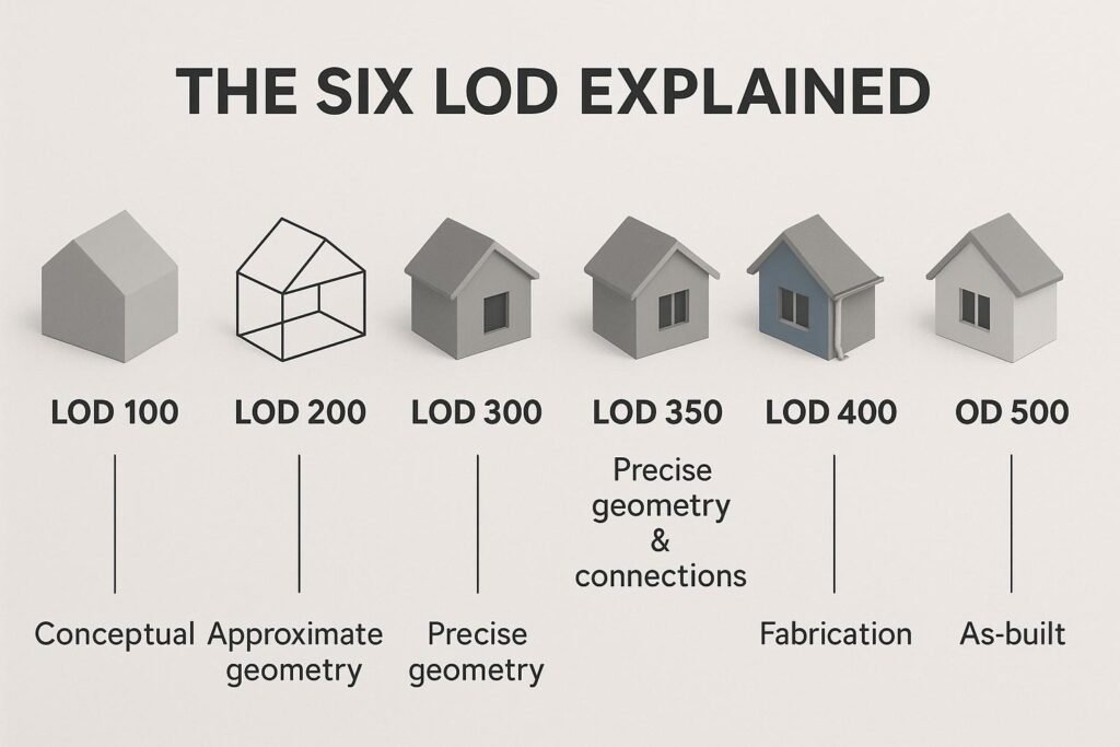
The Six Standard BIM Detail Levels
LOD 100: Conceptual Design
Purpose: Represents basic design intent with approximate volumes, areas, and spatial relationships.
Characteristics:
- Generic placeholders or symbols represent building elements
- Approximate quantities derived from other elements or assumptions
- Used for feasibility studies, massing models, and preliminary cost estimation
Typical Use: Project initiation, site analysis, conceptual design presentations.
Autodesk Application: Create massing families in Revit for early design exploration and spatial analysis.
LOD 200: Schematic Design
Purpose: Refines spatial relationships with approximate quantities, sizes, shapes, and locations.
Characteristics:
- Generic systems represented with approximate dimensions
- Elements include basic properties like material type and general size
- Supports preliminary design decisions and spatial coordination
- Enables early quantity takeoffs with ±30% accuracy
Typical Use: Schematic design, preliminary coordination, early budget estimates during pre-construction planning.
Autodesk Application: Use Revit system families with generic parameters for walls, floors, roofs, and MEP systems.
LOD 300: Detailed Design
Purpose: Provides specific geometry, sizes, shapes, and detailed components for construction documentation.
Characteristics:
- Accurate dimensions, materials, and performance specifications
- Sufficient detail for generating construction documents
- Supports multi-discipline coordination and building details drawings
- Enables quantity takeoffs with ±10-15% accuracy
Typical Use: Construction documents, permit submissions, detailed cost estimation, contractor bidding.
Autodesk Application: Model with specific Revit families including manufacturer-generic components with full dimensional data.
LOD 350: Construction Documentation
Purpose: Bridges detailed design and fabrication with interface information and detailed assemblies.
Characteristics:
- Includes connections, supports, penetrations, and coordination points
- Designed specifically for clash detection between disciplines
- Shows how systems interface and connect
- Essential for generating coordinated shop drawings
Typical Use: Multi-discipline coordination, clash detection, interface management, shop drawing coordination.
Autodesk Application: Use Navisworks for federated model coordination; Revit for detailed connection modeling.
Note: LOD 350 was introduced by BIMForum to fill the gap between design coordination (LOD 300) and fabrication detail (LOD 400).
LOD 400: Fabrication and Assembly
Purpose: Provides fabrication-level detail with specific assemblies, connections, and installation information.
Characteristics:
- LOD 400 in BIM includes exact dimensions, materials, fixing methods, and assembly sequences
- Contains manufacturer-specific components with product data
- Suitable for generating shop drawings and fabrication files
- Supports prefabrication, modular construction, and CNC machining
Typical Use: Shop drawings, fabrication drawings, prefabrication, installation planning during construction execution.
Autodesk Application: Export Revit models to Fabrication CADmep for detailed MEP fabrication; use Advance Steel for structural steel detailing.
LOD 500: As-Built and Facility Management
Purpose: Captures field-verified as-built conditions reflecting actual installed elements.
Characteristics:
- Represents real-world conditions verified on site
- Includes commissioning data, operational parameters, and maintenance information
- Integrates with facility management and BIM management systems
- Contains warranty data, equipment specifications, and replacement schedules
Typical Use: As-built documentation, facility operations, maintenance planning, future renovations, digital twin integration.
Autodesk Application: Use Autodesk Construction Cloud and BIM 360 Ops for as-built model handover and facility management.
LOD 600: Operations and Beyond
While not part of the standard BIMForum specification, some organizations define LOD 600 in BIM as an extended operations phase that includes:
- Ongoing facility performance data
- Energy consumption tracking
- Space utilization analytics
- Digital twin integration with IoT sensors
However, LOD 500 remains the highest standardized level in most BIM protocols.
BIM Detail Levels vs. BIM Maturity Levels
It’s important not to confuse BIM detail levels (LOD) with BIM maturity levels (Level 0-3):
| Aspect | BIM Detail Levels (LOD) | BIM Maturity Levels |
| Definition | Completeness and accuracy of model elements | Degree of collaboration and information sharing |
| Focus | Model element development | Process integration and data exchange |
| Range | LOD 100-500 | Level 0-3 (UK framework) |
| Application | Defines model reliability per project phase | Defines organizational BIM capability |
Level of Information BIM: Beyond Geometry
Modern level of information BIM standards recognize that LOD includes both geometric and non-geometric data
Geometric Information:
- Shape, size, location, orientation
- Connections, assemblies, interfaces
Non-Geometric Information:
- Material specifications, performance criteria
- Cost data, manufacturer details
- Installation instructions, maintenance schedules
- Warranty information, commissioning data
Autodesk Revit parameters, schedules, and shared parameters enable teams to embed rich level of information BIM data at appropriate LOD stages.
Best Practices for Managing BIM Detail Levels
1. Define LOD Requirements in BIM Execution Plan
Establish clear LOD expectations for each discipline and project phase in your BEP to prevent over-modeling or gaps.
2. Align LOD with Project Stages
Match BIM detail levels in construction to project phases: LOD 200 for schematic design, LOD 300 for construction documents, LOD 400 for fabrication.
3. Use LOD for Clash Detection
LOD 350 provides optimal detail for meaningful coordination without excessive file sizes or modeling time.
4. Standardize Revit Families by LOD
Create family templates at different LOD levels to ensure consistency across projects and teams.
5. Communicate LOD in Drawings
Reference LOD levels on building details drawings and specifications so contractors understand model reliability.
6. Track LOD Progression
Use BIM management protocols to document when elements progress from one LOD to another.
7. Integrate LOD with Cost Estimation
Link LOD milestones to cost estimation accuracy targets: ±30% at LOD 200, ±10% at LOD 300, ±5% at LOD 400.
Common BIM Detail Level Mistakes to Avoid
- Over-modeling Early: Creating LOD 400 detail during schematic design wastes time and creates coordination challenges.
- Under-modeling Late: Insufficient detail at fabrication stage causes RFIs and rework.
- Inconsistent LOD Across Disciplines: Mixing LOD 300 architectural with LOD 200 structural creates coordination gaps.
- Ignoring Non-Geometric Data: Focusing only on geometry misses the level of information BIM elements should contain.
- No LOD Documentation: Failing to specify LOD in contracts leads to scope disputes and deliverable confusion.
How AMC Engineer Manages BIM Detail Levels
- LOD-Specific Deliverables: Clear progression from LOD 200 concept models through LOD 500 as-builts aligned with project stages
- Disciplined Modeling Standards: Revit families and templates organized by LOD for consistency and efficiency
- Coordinated LOD 350: Clash-free multi-discipline coordination with optimal detail for detection accuracy
- Fabrication-Ready LOD 400: Shop-drawing-level models for seamless
- Integrated BIM Management: Comprehensive BIM management protocols tracking LOD progression and information quality
💡 At AMC Engineer, we implement rigorous BIM detail levels in construction workflows using professional BIM modeling services with Autodesk Revit, Navisworks, and Construction Cloud
Conclusion
Understanding BIM detail levels is fundamental to successful AEC project delivery. By aligning LOD 100-500 with project phases, coordinating disciplines at appropriate detail levels, and managing both geometric and non-geometric level of information BIM data, teams achieve better coordination, accurate, and seamless handover. Autodesk tools provide the platform, but strategic LOD management ensures your BIM models deliver maximum value throughout the project lifecycle.